
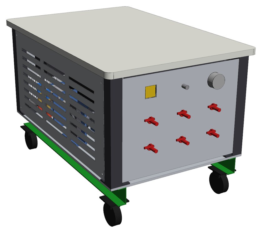
Global Energy DIY vacuum pump cart: front panel with six hose ports and valves |
DIY Vacuum Pump Cart Plans $99.95 (Kits Available) A mobile, oil-free reciprocating vacuum pump built into a sturdy work cart. Four 3-1/2 in bore air cylinders run on a two-throw crankshaft, driven by a 1 hp 3-phase motor through a 10:1 worm gearbox and a variable frequency drive (VFD). It plugs into a standard US 240 V single-phase outlet. The front panel has six hose ports, each with its own on/off ball valve, plus a vacuum gauge, an adjustable vacuum switch and a bleed valve. The 1 in HDPE top makes a handy bench, and the vented side panels lift off for service. What you get with the plans (instant download after payment):
Plans do not include support (or consulting). License is for one build. Production licening available. |
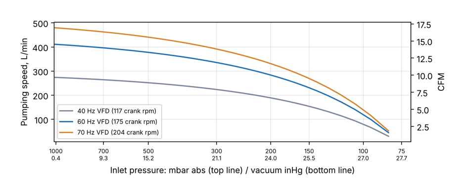
Vacuum pump cart pumping speed vs vacuum, imperial and metric |
Performance: 14.6 CFM and about 27 inHg
AUTO mode stops the pump when the bag reaches the set vacuum and restarts it only to top up leaks. That saves energy and wear on long holds. Performance figures are engineering estimates from simulation; the first build will confirm them. |
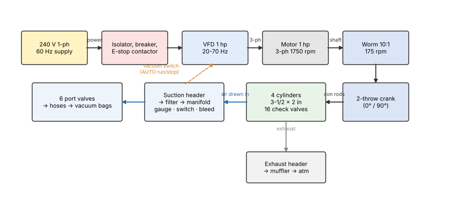
How the 4-cylinder vacuum pump cart works |
How It Works The VFD runs the motor at any speed from about 20 to 70 Hz. The worm gearbox turns the crankshaft at 175 rpm at 60 Hz. Each crank throw drives two opposed cylinders, and the two throws are 90 degrees apart, so the load stays smooth. Every cylinder pumps on both strokes. Low-cracking check valves sit right on the cylinder ports to keep trapped air to a minimum, because trapped air is what limits ultimate vacuum. Air is drawn from the bags through the port valves, the manifold and a filter, then pushed out through an exhaust muffler. Because it is a dry pump, there is no oil to change and no oil mist. |
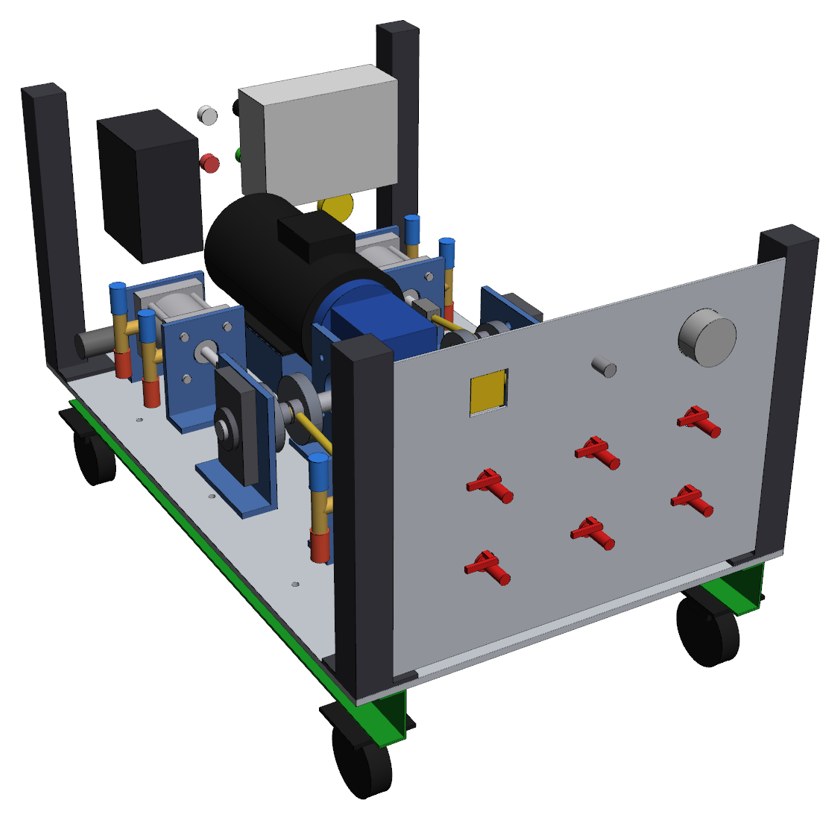
Inside the vacuum pump cart: drivetrain, cylinders and front manifold |
Inside the Cart Four corner posts give plenty of room for the drivetrain below the work top. The lower deck carries the motor, gearbox, outboard bearings, cylinders and valve tees. The front panel manifold feeds the six hose ports. The drawings use common shop materials: 3/8 in aluminium deck, 2 in square steel posts, angle top rails, 0.063 and 0.125 in aluminium panels, and 1 in HDPE. |
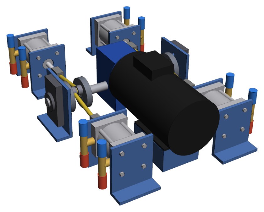
Vacuum pump drivetrain: 1 hp motor, 10:1 worm gearbox, crankshaft and four cylinders |
Drivetrain: Motor, Worm Gearbox, Crankshaft, Four Cylinders The built-up crankshaft uses simple turned parts: a main shaft through the gearbox's hollow bore, four crank webs, two crank pins and two stub shafts in flange bearings. Standard ball-joint rod ends and threaded rods make adjustable con rods, so each piston can be set to stop just short of the end caps. The motor, gearbox, cylinders, bearings and VFD are catalog parts from AutomationDirect, McMaster-Carr and bearing suppliers, all listed in the BOM. |
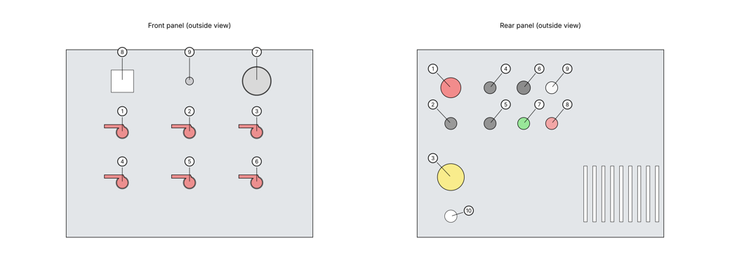
Front vacuum panel and rear control panel layout |
Simple Controls Front: six port valves, vacuum gauge, vacuum switch, bleed valve. Rear: E-stop, lockable isolator, POWER ON, HAND-OFF-AUTO selector, BOOST (70 Hz), speed knob, and RUN / FAULT / POWER lights. The VFD mounts behind the rear panel. The included wiring diagram covers the complete 240 V single-phase VFD installation, with the E-stop and the vacuum-switch AUTO circuit. |
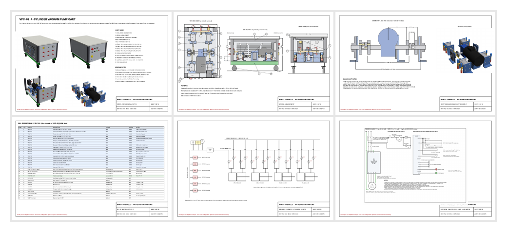
Sample pages from the vacuum pump cart drawing set |
Sample Pages from the Drawing Set The drawing set has 14 sheets: cover and index, general arrangement with BOM balloons, crankshaft assembly, bill of materials, detail drawings for each fabricated part, deck hole table, front and rear panel layouts, pneumatic schematic, electrical diagram and performance charts. The STEP files open in SolidWorks, Fusion 360, FreeCAD, Onshape and most CNC/CAM software. |
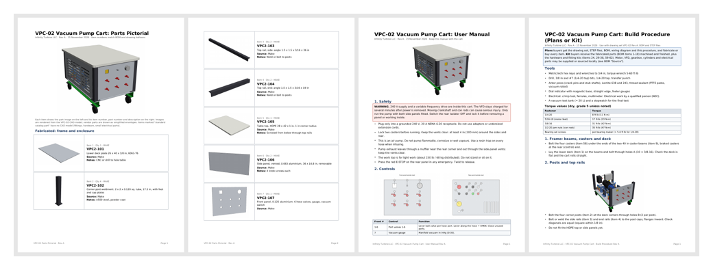
Sample pages: parts pictorial, user manual and build procedure |
Parts Pictorial, User Manual and Build Procedure Parts pictorial: an image of every part with its item number and description, for ordering and kit checking. User manual: safety, controls, operation in HAND and AUTO, maintenance schedule, troubleshooting and VFD settings. Build procedure: twelve steps from frame to final vacuum test, with tool list, torque table and a test record. |
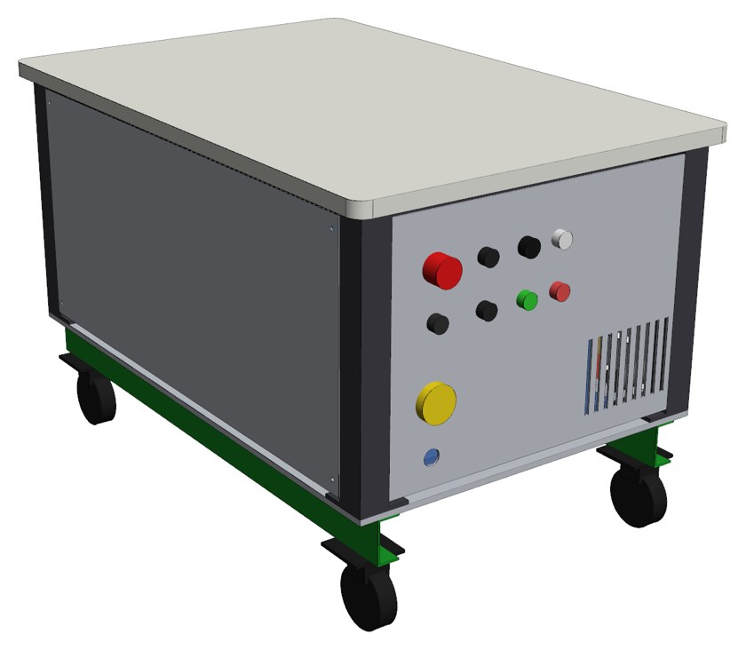
Vacuum pump cart rear control panel with E-stop and VFD |
Applications
Not for flammable or corrosive vapours. Use a resin trap when infusing. |
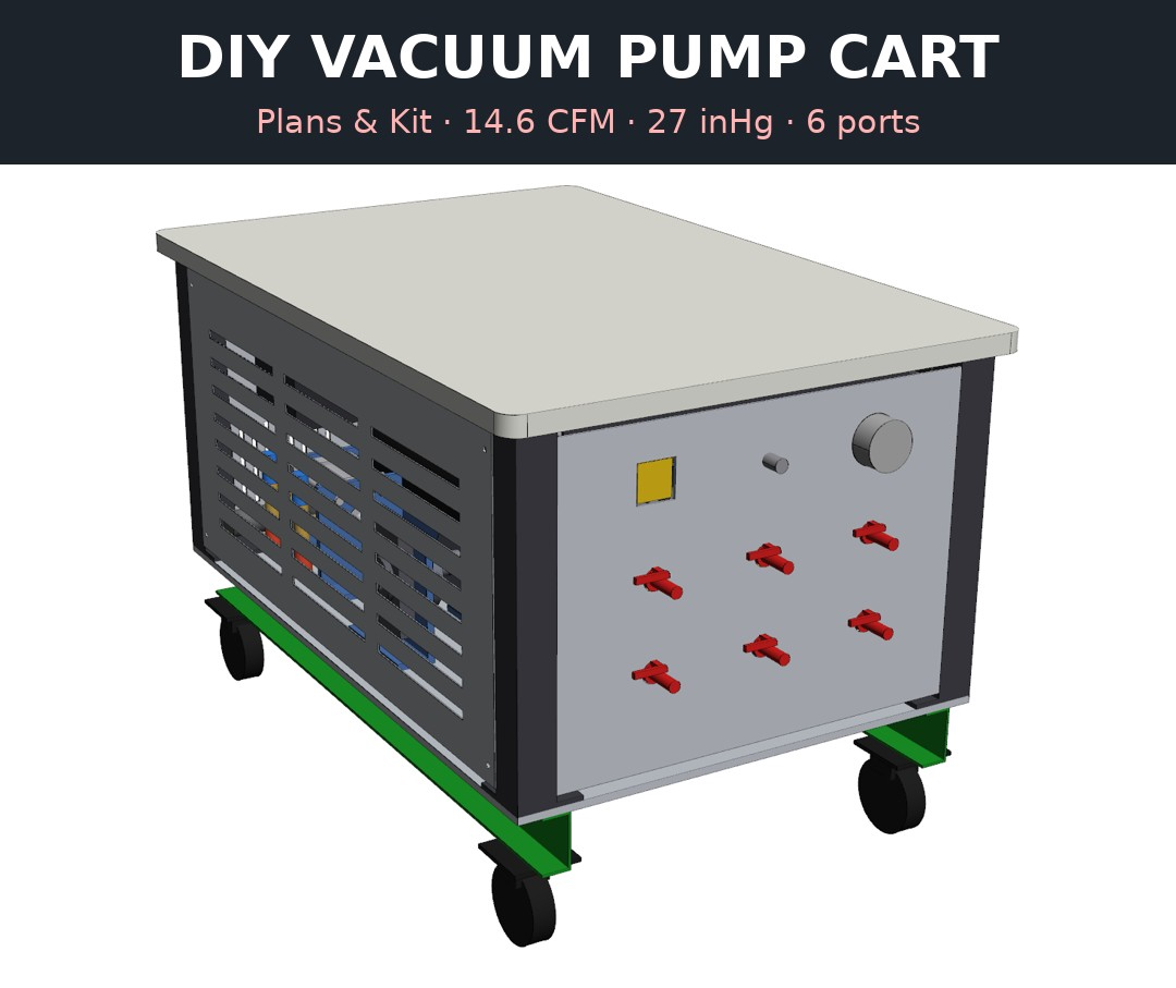
Vacuum pump cart plans and kit options |
Plans, Kit, or Full Build Plans $99.95: complete digital package (drawings, STEP CAD, BOM, manuals). Build it yourself and buy the parts locally. Kit: machined and finished fabricated parts (deck, posts, rails, HDPE top, panels, crankshaft parts, brackets) plus hardware and fitting kits. Add your own motor, VFD, gearbox and cylinders, or ask us to supply them. Email for a quote. Full build: assembled and tested. Email for a quote. |
| CONTACT Email: greg@globalmicroturbine.com | AMP | PDF |