PDF Publication Title:
Text from PDF Page: 088
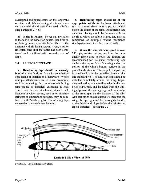
AC 43.13-1B 9/8/98 overlapped and doped seams on the longerons or other wide fabric-forming structures in ac cordance with the aircraft Vne speed. (Refer ence paragraph 2-7 b.) d. Holes in Fabric. Never cut any holes in the fabric for inspection panels, spar fittings, or drain grommets; or attach the fabric to the airframe with rib lacing screws, rivets, clips, or rib stitch cord until the fabric has been semi- tauted and stabilized with several coats of dope. 2-9. REINFORCING TAPE. a. Reinforcing tape should be securely bonded to the fabric surface with dope before cord lacing or installation of hardware. Where multiple attachments are in close proximity, such as on a wing rib, continuous reinforcing tape should be installed, extending at least 1 inch past the last attachment at each end. Random or wide spacing, such as on fuselage stringers or empennage surfaces, may be rein forced with 2-inch lengths of reinforcing tape centered on the attachment location. b. Reinforcing tapes should be of the appropriate width for hardware attachment such as screws, rivets, wire clips, etc., which pierce the center of the tape. Reinforcing tape under cord lacing should be the same width as the rib to which the fabric is laced and may be comprised of multiple widths positioned side-by-side to achieve the required width. c. When the aircraft Vne speed is over 250 mph, anti-tear strips, cut from the same quality fabric used to cover the aircraft, are recommended for use under reinforcing tape on the entire top surface of the wing and on the portion of the wing’s bottom surface in the propeller slipstream. The propeller slipstream is considered to be the propeller diameter plus one outboard rib. The anti-tear strip should be installed completely around the wing, begin ning and ending at the trailing edge in the pro peller slipstream, and installed from the trail ing edge over the leading edge and back under to the front spar on the balance of the ribs. Anti-tear strips should extend 1/2 inch past the wing rib cap edges and be thoroughly bonded to the fabric with dope before the reinforcing tape is installed. (See figure 2-3.) FIGURE 2-3. Exploded side view of rib. Page 2-10 Par 2-8PDF Image | AFS-640
PDF Search Title:
AFS-640Original File Name Searched:
ac_43.13-1b_w-chg1.pdfDIY PDF Search: Google It | Yahoo | Bing
5,000 BF Shipping Container Lumber Dry Kiln For Quality Lumber The 5,000 BF container kiln consists of one 40 foot high-cube aluminum shipping container... More Info
Shipping Container Lumber Dry Kilns by Global Energy Global Energy designed and developed the container kiln back in 1991. The purpose is to give access to portable sawmill owners, furniture makers, and small business the value added profit of dry kiln lumber and quality hardwoods... More Info
Vacuum Kiln Conversion Kit for Lumber and Wood Dry Kilns Convert your existing conventional dry kiln into a fast drying vacuum kiln. Similar to vacuum bagging in the boat building and aircraft industry, we have come up with a proprietary process which allows you to build a very simple vacuum kiln at a fraction of the price, and without the intensive conventional metal chamber structure... More Info
Vacuum Pump Cart System for Bagging Clamping Wood Drying and more Vacuum Cart with 2HP Pump and Dual Pistons with multiple multiplex vacuum ports and liquid reservoir... More Info
Vacuum Bagging Basics Vacuum bagging is a method of clamping, which has traditionally been used in the composites industry, but can also be used for vacuum drying materials, including wood products... More Info
| CONTACT TEL: 608-238-6001 Email: greg@globalmicroturbine.com | RSS | AMP |