PDF Publication Title:
Text from PDF Page: 341
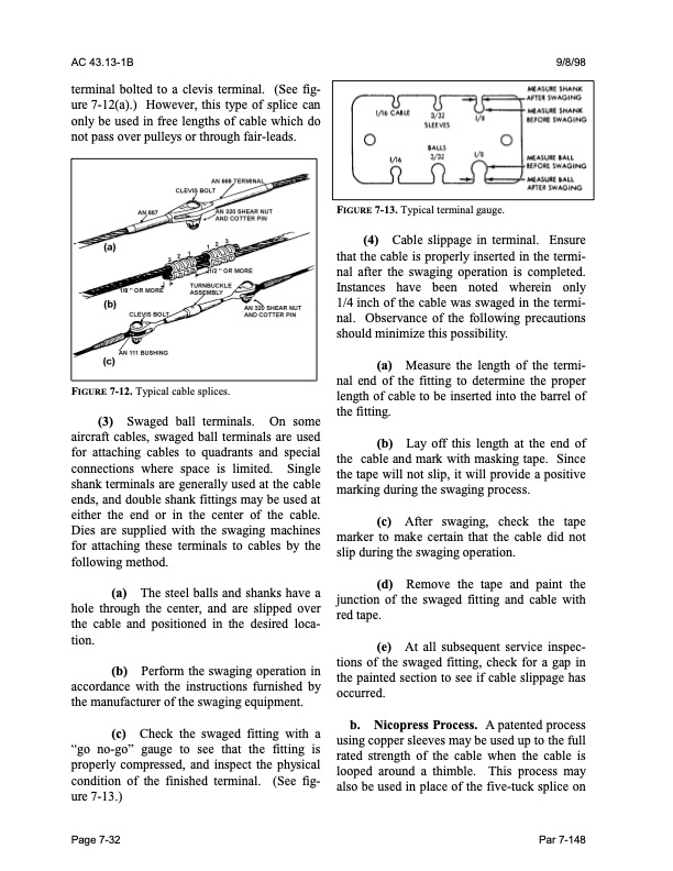
AC 43.13-1B 9/8/98 terminal bolted to a clevis terminal. (See fig ure 7-12(a).) However, this type of splice can only be used in free lengths of cable which do not pass over pulleys or through fair-leads. FIGURE 7-12. Typical cable splices. (3) Swaged ball terminals. On some aircraft cables, swaged ball terminals are used for attaching cables to quadrants and special connections where space is limited. Single shank terminals are generally used at the cable ends, and double shank fittings may be used at either the end or in the center of the cable. Dies are supplied with the swaging machines for attaching these terminals to cables by the following method. (a) The steel balls and shanks have a hole through the center, and are slipped over the cable and positioned in the desired loca tion. (b) Perform the swaging operation in accordance with the instructions furnished by the manufacturer of the swaging equipment. (c) Check the swaged fitting with a “go no-go” gauge to see that the fitting is properly compressed, and inspect the physical condition of the finished terminal. (See fig ure 7-13.) FIGURE 7-13. Typical terminal gauge. (4) Cable slippage in terminal. Ensure that the cable is properly inserted in the termi nal after the swaging operation is completed. Instances have been noted wherein only 1/4 inch of the cable was swaged in the termi nal. Observance of the following precautions should minimize this possibility. (a) Measure the length of the termi nal end of the fitting to determine the proper length of cable to be inserted into the barrel of the fitting. (b) Lay off this length at the end of the cable and mark with masking tape. Since the tape will not slip, it will provide a positive marking during the swaging process. (c) After swaging, check the tape marker to make certain that the cable did not slip during the swaging operation. (d) Remove the tape and paint the junction of the swaged fitting and cable with red tape. (e) At all subsequent service inspec tions of the swaged fitting, check for a gap in the painted section to see if cable slippage has occurred. b. Nicopress Process. A patented process using copper sleeves may be used up to the full rated strength of the cable when the cable is looped around a thimble. This process may also be used in place of the five-tuck splice on Page 7-32 Par 7-148PDF Image | AFS-640
PDF Search Title:
AFS-640Original File Name Searched:
ac_43.13-1b_w-chg1.pdfDIY PDF Search: Google It | Yahoo | Bing
5,000 BF Shipping Container Lumber Dry Kiln For Quality Lumber The 5,000 BF container kiln consists of one 40 foot high-cube aluminum shipping container... More Info
Shipping Container Lumber Dry Kilns by Global Energy Global Energy designed and developed the container kiln back in 1991. The purpose is to give access to portable sawmill owners, furniture makers, and small business the value added profit of dry kiln lumber and quality hardwoods... More Info
Vacuum Kiln Conversion Kit for Lumber and Wood Dry Kilns Convert your existing conventional dry kiln into a fast drying vacuum kiln. Similar to vacuum bagging in the boat building and aircraft industry, we have come up with a proprietary process which allows you to build a very simple vacuum kiln at a fraction of the price, and without the intensive conventional metal chamber structure... More Info
Vacuum Pump Cart System for Bagging Clamping Wood Drying and more Vacuum Cart with 2HP Pump and Dual Pistons with multiple multiplex vacuum ports and liquid reservoir... More Info
Vacuum Bagging Basics Vacuum bagging is a method of clamping, which has traditionally been used in the composites industry, but can also be used for vacuum drying materials, including wood products... More Info
| CONTACT TEL: 608-238-6001 Email: greg@globalmicroturbine.com | RSS | AMP |