PDF Publication Title:
Text from PDF Page: 340
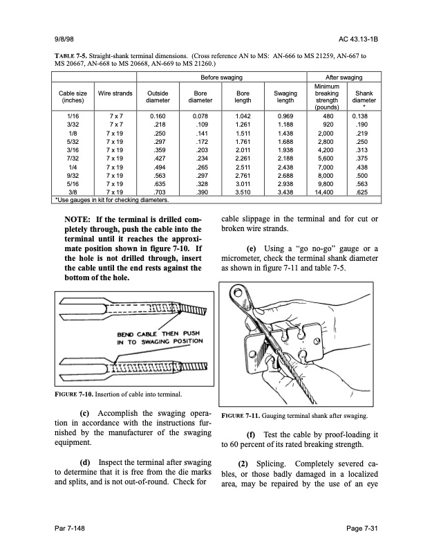
9/8/98 AC 43.13-1B TABLE 7-5. Straight-shank terminal dimensions. (Cross reference AN to MS: AN-666 to MS 21259, AN-667 to MS 20667, AN-668 to MS 20668, AN-669 to MS 21260.) Before swaging After swaging Cable size (inches) Wire strands Outside diameter Bore diameter Bore length Swaging length Minimum breaking strength (pounds) Shank diameter * 1/16 3/32 1/8 5/32 3/16 7/32 1/4 9/32 5/16 3/8 7x7 7x7 7 x 19 7 x 19 7 x 19 7 x 19 7 x 19 7 x 19 7 x 19 7 x 19 0.160 .218 .250 .297 .359 .427 .494 .563 .635 .703 0.078 .109 .141 .172 .203 .234 .265 .297 .328 .390 1.042 1.261 1.511 1.761 2.011 2.261 2.511 2.761 3.011 3.510 0.969 1.188 1.438 1.688 1.938 2.188 2.438 2.688 2.938 3.438 480 920 2,000 2,800 4,200 5,600 7,000 8,000 9,800 14,400 0.138 .190 .219 .250 .313 .375 .438 .500 .563 .625 *Use gauges in kit for checking diameters. NOTE: If the terminal is drilled com- pletely through, push the cable into the terminal until it reaches the approxi- mate position shown in figure 7-10. If the hole is not drilled through, insert the cable until the end rests against the bottom of the hole. cable slippage in the terminal and for cut or broken wire strands. (e) Using a “go no-go” gauge or a micrometer, check the terminal shank diameter as shown in figure 7-11 and table 7-5. FIGURE 7-11. Gauging terminal shank after swaging. (f) Test the cable by proof-loading it to 60 percent of its rated breaking strength. (2) Splicing. Completely severed ca bles, or those badly damaged in a localized area, may be repaired by the use of an eye FIGURE 7-10. Insertion of cable into terminal. (c) Accomplish the swaging opera tion in accordance with the instructions fur nished by the manufacturer of the swaging equipment. (d) Inspect the terminal after swaging to determine that it is free from the die marks and splits, and is not out-of-round. Check for Par 7-148 Page 7-31PDF Image | AFS-640
PDF Search Title:
AFS-640Original File Name Searched:
ac_43.13-1b_w-chg1.pdfDIY PDF Search: Google It | Yahoo | Bing
5,000 BF Shipping Container Lumber Dry Kiln For Quality Lumber The 5,000 BF container kiln consists of one 40 foot high-cube aluminum shipping container... More Info
Shipping Container Lumber Dry Kilns by Global Energy Global Energy designed and developed the container kiln back in 1991. The purpose is to give access to portable sawmill owners, furniture makers, and small business the value added profit of dry kiln lumber and quality hardwoods... More Info
Vacuum Kiln Conversion Kit for Lumber and Wood Dry Kilns Convert your existing conventional dry kiln into a fast drying vacuum kiln. Similar to vacuum bagging in the boat building and aircraft industry, we have come up with a proprietary process which allows you to build a very simple vacuum kiln at a fraction of the price, and without the intensive conventional metal chamber structure... More Info
Vacuum Pump Cart System for Bagging Clamping Wood Drying and more Vacuum Cart with 2HP Pump and Dual Pistons with multiple multiplex vacuum ports and liquid reservoir... More Info
Vacuum Bagging Basics Vacuum bagging is a method of clamping, which has traditionally been used in the composites industry, but can also be used for vacuum drying materials, including wood products... More Info
| CONTACT TEL: 608-238-6001 Email: greg@globalmicroturbine.com | RSS | AMP |