PDF Publication Title:
Text from PDF Page: 470
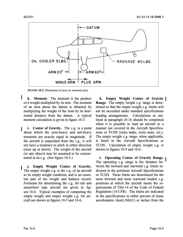
9/27/01 AC 43.13-1B CHG 1 FIGURE 10-2. Illustration of arm (or moment arm). h. Moment. The moment is the product of a weight multiplied by its arm. The moment of an item about the datum is obtained by multiplying the weight of the item by its hori- zontal distance from the datum. A typical moment calculation is given in figure 10-3. i. Center of Gravity. The c.g. is a point about which the nose-heavy and tail-heavy moments are exactly equal in magnitude. If the aircraft is suspended from the c.g., it will not have a tendency to pitch in either direction (nose up or down). The weight of the aircraft (or any object) may be assumed to be concen- trated at its c.g. (See figure 10-3.) j. Empty Weight Center of Gravity. The empty weight c.g. is the c.g. of an aircraft in its empty weight condition, and is an essen- tial part of the weight and balance record. Formulas for determining the c.g. for tail and nosewheel type aircraft are given in fig- ure 10-4. Typical examples of computing the empty weight and empty weight c.g. for air- craft are shown in figures 10-5 and 10-6. k. Empty Weight Center of Gravity Range. The empty weight c.g. range is deter- mined so that the empty weight c.g. limits will not be exceeded under standard specifications loading arrangements. Calculations as out- lined in paragraph 10-16 should be completed when it is possible to load an aircraft in a manner not covered in the Aircraft Specifica- tions or TCDS (extra tanks, extra seats, etc.). The empty weight c.g. range, when applicable, is listed in the Aircraft Specifications or TCDS. Calculation of empty weight c.g. is shown in figures 10-5 and 10-6. l. Operating Center of Gravity Range. The operating c.g. range is the distance be- tween the forward and rearward c.g. limits in- dicated in the pertinent Aircraft Specifications or TCDS. These limits are determined for the most forward and most rearward loaded c.g. positions at which the aircraft meets the re- quirements of Title 14 of the Code of Federal Regulation (14 CFR). The limits are indicated in the specifications in either percent of mean aerodynamic chord (MAC) or inches from the Par 10-2 Page 10-3PDF Image | AFS-640
PDF Search Title:
AFS-640Original File Name Searched:
ac_43.13-1b_w-chg1.pdfDIY PDF Search: Google It | Yahoo | Bing
5,000 BF Shipping Container Lumber Dry Kiln For Quality Lumber The 5,000 BF container kiln consists of one 40 foot high-cube aluminum shipping container... More Info
Shipping Container Lumber Dry Kilns by Global Energy Global Energy designed and developed the container kiln back in 1991. The purpose is to give access to portable sawmill owners, furniture makers, and small business the value added profit of dry kiln lumber and quality hardwoods... More Info
Vacuum Kiln Conversion Kit for Lumber and Wood Dry Kilns Convert your existing conventional dry kiln into a fast drying vacuum kiln. Similar to vacuum bagging in the boat building and aircraft industry, we have come up with a proprietary process which allows you to build a very simple vacuum kiln at a fraction of the price, and without the intensive conventional metal chamber structure... More Info
Vacuum Pump Cart System for Bagging Clamping Wood Drying and more Vacuum Cart with 2HP Pump and Dual Pistons with multiple multiplex vacuum ports and liquid reservoir... More Info
Vacuum Bagging Basics Vacuum bagging is a method of clamping, which has traditionally been used in the composites industry, but can also be used for vacuum drying materials, including wood products... More Info
| CONTACT TEL: 608-238-6001 Email: greg@globalmicroturbine.com | RSS | AMP |