PDF Publication Title:
Text from PDF Page: 416
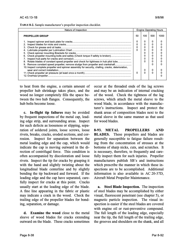
AC 43.13-1B 9/8/98 TABLE 8-2. Sample manufacturer’s propeller inspection checklist. Nature of Inspection PROPELLER GROUP 1. Inspectspinnerandbackplateforcracks.................................................................................... 2. Inspectbladesfornicksandcracks............................................................................................. 3. Checkforgreaseandoilleaks..................................................................................................... 4. LubricatepropellerperLubricationChart..................................................................................... 5. CheckspinnermountingBracketsforcracks............................................................................... 6. Checkpropellermountingboltsandsafety(Checktorqueifsafetyisbroken)............................. 7. Inspecthubpartsforcracksandcorrosion.................................................................................. 8. Rotatebladesofconstantspeedpropellerandcheckfortightnessinhubpilottube.................... 9. Removeconstantspeedpropeller;removesludgefrompropellerandcrankshaft........................ 10. Inspect complete propeller and spinner assembly for security, chafing, cracks, deterioration, wear and correct installation........................................................................................................ 11. Check propeller air pressure (at least once a month)................................................................... 12. Overhaul propeller....................................................................................................................... to heat from the engine, a certain amount of propeller hub shrinkage takes place, and the wood no longer completely fills the space be- tween the two hub flanges. Consequently, the hub bolts become loose. c. In-flight tip failures may be avoided by frequent inspections of the metal cap, lead- ing edge strip, and surrounding areas. Inspect for such defects as looseness or slipping, sepa- ration of soldered joints, loose screws, loose rivets, breaks, cracks, eroded sections, and cor- rosion. Inspect for separation between the metal leading edge and the cap, which would indicate the cap is moving outward in the di- rection of centrifugal force. This condition is often accompanied by discoloration and loose rivets. Inspect the tip for cracks by grasping it with the hand and slightly twisting about the longitudinal blade centerline and by slightly bending the tip backward and forward. If the leading edge and the cap have separated, care- fully inspect for cracks at this point. Cracks usually start at the leading edge of the blade. A fine line appearing in the fabric or plastic may indicate a crack in the wood. Check the trailing edge of the propeller blades for bond- ing, separation, or damage. d. Examine the wood close to the metal sleeve of wood blades for cracks extending outward on the blade. These cracks sometimes Engine Operating Hours 50 100 500 000 000 000 000 00 00 00 00 0 00 000 occur at the threaded ends of the lag screws and may be an indication of internal cracking of the wood. Check the tightness of the lag screws, which attach the metal sleeve to the wood blade, in accordance with the manufac- turer’s instructions. Inspect and protect the shank areas of composition blades next to the metal sleeve in the same manner as that used for wood blades. 8-93. METAL PROPELLERS AND BLADES. These propellers and blades are generally susceptible to fatigue failure result- ing from the concentration of stresses at the bottoms of sharp nicks, cuts, and scratches. It is necessary, therefore, to frequently and care- fully inspect them for such injuries. Propeller manufacturers publish SB’s and instructions which prescribe the manner in which these in- spections are to be accomplished. Additional information is also available in AC 20-37D, Aircraft Metal Propeller Maintenance. a. Steel Blade Inspection. The inspection of steel blades may be accomplished by either visual, fluorescent penetrant (see chapter 5), or magnetic particle inspection. The visual in- spection is easier if the steel blades are covered with engine oil or rust-preventive compound. The full length of the leading edge, especially near the tip, the full length of the trailing edge, the grooves and shoulders on the shank, and all Page 8-38 Par 8-92 1000 0 0 0 0 0 0 0 0 0 0 0 0PDF Image | AFS-640
PDF Search Title:
AFS-640Original File Name Searched:
ac_43.13-1b_w-chg1.pdfDIY PDF Search: Google It | Yahoo | Bing
5,000 BF Shipping Container Lumber Dry Kiln For Quality Lumber The 5,000 BF container kiln consists of one 40 foot high-cube aluminum shipping container... More Info
Shipping Container Lumber Dry Kilns by Global Energy Global Energy designed and developed the container kiln back in 1991. The purpose is to give access to portable sawmill owners, furniture makers, and small business the value added profit of dry kiln lumber and quality hardwoods... More Info
Vacuum Kiln Conversion Kit for Lumber and Wood Dry Kilns Convert your existing conventional dry kiln into a fast drying vacuum kiln. Similar to vacuum bagging in the boat building and aircraft industry, we have come up with a proprietary process which allows you to build a very simple vacuum kiln at a fraction of the price, and without the intensive conventional metal chamber structure... More Info
Vacuum Pump Cart System for Bagging Clamping Wood Drying and more Vacuum Cart with 2HP Pump and Dual Pistons with multiple multiplex vacuum ports and liquid reservoir... More Info
Vacuum Bagging Basics Vacuum bagging is a method of clamping, which has traditionally been used in the composites industry, but can also be used for vacuum drying materials, including wood products... More Info
| CONTACT TEL: 608-238-6001 Email: greg@globalmicroturbine.com | RSS | AMP |