PDF Publication Title:
Text from PDF Page: 402
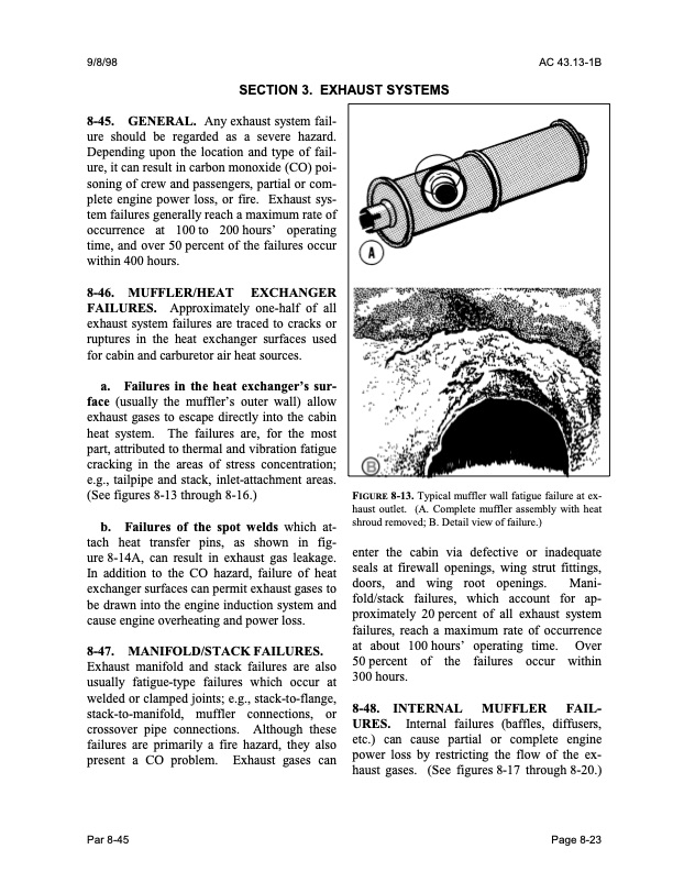
9/8/98 AC 43.13-1B SECTION 3. EXHAUST SYSTEMS 8-45. GENERAL. Any exhaust system fail- ure should be regarded as a severe hazard. Depending upon the location and type of fail- ure, it can result in carbon monoxide (CO) poi- soning of crew and passengers, partial or com- plete engine power loss, or fire. Exhaust sys- tem failures generally reach a maximum rate of occurrence at 100 to 200 hours’ operating time, and over 50 percent of the failures occur within 400 hours. 8-46. MUFFLER/HEAT EXCHANGER FAILURES. Approximately one-half of all exhaust system failures are traced to cracks or ruptures in the heat exchanger surfaces used for cabin and carburetor air heat sources. a. Failures in the heat exchanger’s sur- face (usually the muffler’s outer wall) allow exhaust gases to escape directly into the cabin heat system. The failures are, for the most part, attributed to thermal and vibration fatigue cracking in the areas of stress concentration; e.g., tailpipe and stack, inlet-attachment areas. (See figures 8-13 through 8-16.) b. Failures of the spot welds which at- tach heat transfer pins, as shown in fig- ure 8-14A, can result in exhaust gas leakage. In addition to the CO hazard, failure of heat exchanger surfaces can permit exhaust gases to be drawn into the engine induction system and cause engine overheating and power loss. 8-47. MANIFOLD/STACK FAILURES. Exhaust manifold and stack failures are also usually fatigue-type failures which occur at welded or clamped joints; e.g., stack-to-flange, stack-to-manifold, muffler connections, or crossover pipe connections. Although these failures are primarily a fire hazard, they also present a CO problem. Exhaust gases can FIGURE 8-13. Typical muffler wall fatigue failure at ex- haust outlet. (A. Complete muffler assembly with heat shroud removed; B. Detail view of failure.) enter the cabin via defective or inadequate seals at firewall openings, wing strut fittings, doors, and wing root openings. Mani- fold/stack failures, which account for ap- proximately 20 percent of all exhaust system failures, reach a maximum rate of occurrence Par 8-45 Page 8-23 at about 100 hours’ operating failures time. occur Over within 50 percent 300 hours. of the 8-48. INTERNAL URES. Internal failures (baffles, diffusers, etc.) can cause partial or complete engine power loss by restricting the flow of the ex- haust gases. (See figures 8-17 through 8-20.) MUFFLER FAIL-PDF Image | AFS-640
PDF Search Title:
AFS-640Original File Name Searched:
ac_43.13-1b_w-chg1.pdfDIY PDF Search: Google It | Yahoo | Bing
5,000 BF Shipping Container Lumber Dry Kiln For Quality Lumber The 5,000 BF container kiln consists of one 40 foot high-cube aluminum shipping container... More Info
Shipping Container Lumber Dry Kilns by Global Energy Global Energy designed and developed the container kiln back in 1991. The purpose is to give access to portable sawmill owners, furniture makers, and small business the value added profit of dry kiln lumber and quality hardwoods... More Info
Vacuum Kiln Conversion Kit for Lumber and Wood Dry Kilns Convert your existing conventional dry kiln into a fast drying vacuum kiln. Similar to vacuum bagging in the boat building and aircraft industry, we have come up with a proprietary process which allows you to build a very simple vacuum kiln at a fraction of the price, and without the intensive conventional metal chamber structure... More Info
Vacuum Pump Cart System for Bagging Clamping Wood Drying and more Vacuum Cart with 2HP Pump and Dual Pistons with multiple multiplex vacuum ports and liquid reservoir... More Info
Vacuum Bagging Basics Vacuum bagging is a method of clamping, which has traditionally been used in the composites industry, but can also be used for vacuum drying materials, including wood products... More Info
| CONTACT TEL: 608-238-6001 Email: greg@globalmicroturbine.com | RSS | AMP |