PDF Publication Title:
Text from PDF Page: 387
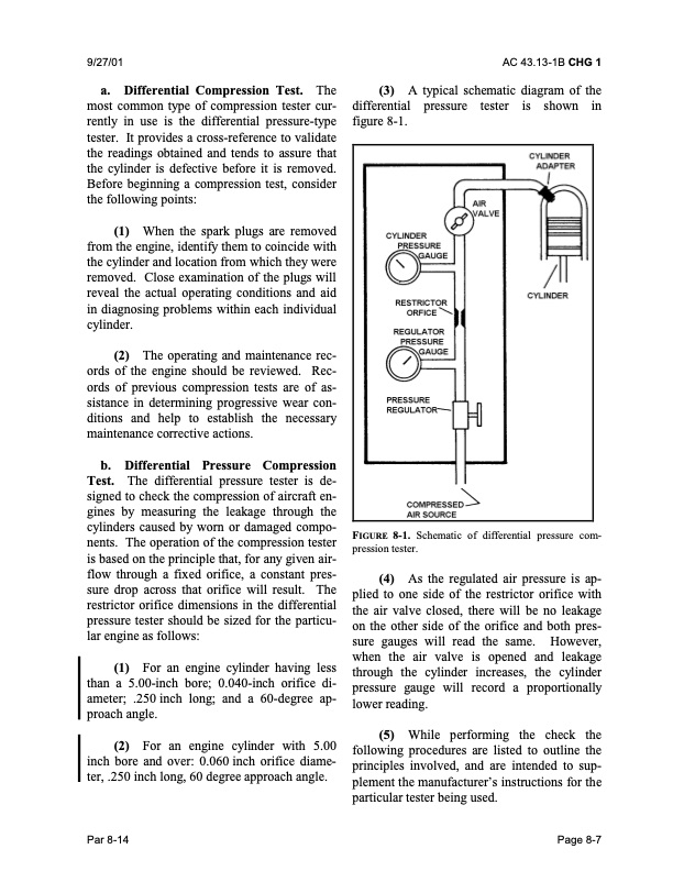
9/27/01 AC 43.13-1B CHG 1 a. Differential Compression Test. The most common type of compression tester cur- rently in use is the differential pressure-type tester. It provides a cross-reference to validate the readings obtained and tends to assure that the cylinder is defective before it is removed. Before beginning a compression test, consider the following points: (1) When the spark plugs are removed from the engine, identify them to coincide with the cylinder and location from which they were removed. Close examination of the plugs will reveal the actual operating conditions and aid in diagnosing problems within each individual cylinder. (2) The operating and maintenance rec- ords of the engine should be reviewed. Rec- ords of previous compression tests are of as- sistance in determining progressive wear con- ditions and help to establish the necessary maintenance corrective actions. b. Differential Pressure Compression Test. The differential pressure tester is de- signed to check the compression of aircraft en- gines by measuring the leakage through the cylinders caused by worn or damaged compo- nents. The operation of the compression tester is based on the principle that, for any given air- flow through a fixed orifice, a constant pres- sure drop across that orifice will result. The restrictor orifice dimensions in the differential pressure tester should be sized for the particu- lar engine as follows: (1) For an engine cylinder having less than a 5.00-inch bore; 0.040-inch orifice di- ameter; .250 inch long; and a 60-degree ap- proach angle. (2) For an engine cylinder with 5.00 inch bore and over: 0.060 inch orifice diame- ter, .250 inch long, 60 degree approach angle. (3) A typical schematic diagram of the differential pressure tester is shown in figure 8-1. FIGURE 8-1. Schematic of differential pressure com- pression tester. (4) As the regulated air pressure is ap- plied to one side of the restrictor orifice with the air valve closed, there will be no leakage on the other side of the orifice and both pres- sure gauges will read the same. However, when the air valve is opened and leakage through the cylinder increases, the cylinder pressure gauge will record a proportionally lower reading. (5) While performing the check the following procedures are listed to outline the principles involved, and are intended to sup- plement the manufacturer’s instructions for the particular tester being used. Par 8-14 Page 8-7PDF Image | AFS-640
PDF Search Title:
AFS-640Original File Name Searched:
ac_43.13-1b_w-chg1.pdfDIY PDF Search: Google It | Yahoo | Bing
5,000 BF Shipping Container Lumber Dry Kiln For Quality Lumber The 5,000 BF container kiln consists of one 40 foot high-cube aluminum shipping container... More Info
Shipping Container Lumber Dry Kilns by Global Energy Global Energy designed and developed the container kiln back in 1991. The purpose is to give access to portable sawmill owners, furniture makers, and small business the value added profit of dry kiln lumber and quality hardwoods... More Info
Vacuum Kiln Conversion Kit for Lumber and Wood Dry Kilns Convert your existing conventional dry kiln into a fast drying vacuum kiln. Similar to vacuum bagging in the boat building and aircraft industry, we have come up with a proprietary process which allows you to build a very simple vacuum kiln at a fraction of the price, and without the intensive conventional metal chamber structure... More Info
Vacuum Pump Cart System for Bagging Clamping Wood Drying and more Vacuum Cart with 2HP Pump and Dual Pistons with multiple multiplex vacuum ports and liquid reservoir... More Info
Vacuum Bagging Basics Vacuum bagging is a method of clamping, which has traditionally been used in the composites industry, but can also be used for vacuum drying materials, including wood products... More Info
| CONTACT TEL: 608-238-6001 Email: greg@globalmicroturbine.com | RSS | AMP |