PDF Publication Title:
Text from PDF Page: 207
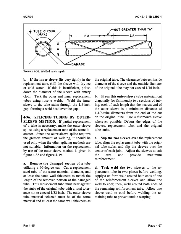
9/27/01 AC 43.13-1B CHG 1 FIGURE 4-36. Welded patch repair. b. If the inner sleeve fits very tightly in the replacement tube, chill the sleeve with dry ice or cold water. If this is insufficient, polish down the diameter of the sleeve with emery cloth. Tack the outer and inner replacement tubes using rosette welds. Weld the inner sleeve to the tube stubs through the 1/8-inch gap, forming a weld bead over the gap. 4-96. SPLICING TUBING BY OUTER SLEEVE METHOD. If partial replacement of a tube is necessary, make the outer-sleeve splice using a replacement tube of the same di ameter. Since the outer-sleeve splice requires the greatest amount of welding, it should be used only when the other splicing methods are not suitable. Information on the replacement by use of the outer-sleeve method is given in figure 4-38 and figure 4-39. a. Remove the damaged section of a tube utilizing a 90-degree cut. Cut a replacement steel tube of the same material, diameter, and at least the same wall thickness to match the length of the removed portion of the damaged tube. This replacement tube must bear against the stubs of the original tube with a total toler ance not to exceed 1/32 inch. The outer-sleeve tube material selected must be of the same material and at least the same wall thickness as the original tube. The clearance between inside diameter of the sleeve and the outside diameter of the original tube may not exceed 1/16 inch. b. From this outer-sleeve tube material, cut diagonally (or fishmouth) two sections of tub ing, each of such length that the nearest end of the outer sleeve is a minimum distance of 1-1/2-tube diameters from the end of the cut on the original tube. Use a fishmouth sleeve wherever possible. Deburr the edges of the sleeves, replacement tube, and the original tube stubs. c. Slip the two sleeves over the replacement tube, align the replacement tube with the origi nal tube stubs, and slip the sleeves over the center of each joint. Adjust the sleeves to suit the area and provide maximum reinforcement. d. Tack weld the two sleeves to the re placement tube in two places before welding. Apply a uniform weld around both ends of one of the reinforcement sleeves and allow the weld to cool; then, weld around both ends of the remaining reinforcement tube. Allow one sleeve weld to cool before welding the re maining tube to prevent undue warping. Par 4-95 Page 4-67PDF Image | AFS-640
PDF Search Title:
AFS-640Original File Name Searched:
ac_43.13-1b_w-chg1.pdfDIY PDF Search: Google It | Yahoo | Bing
5,000 BF Shipping Container Lumber Dry Kiln For Quality Lumber The 5,000 BF container kiln consists of one 40 foot high-cube aluminum shipping container... More Info
Shipping Container Lumber Dry Kilns by Global Energy Global Energy designed and developed the container kiln back in 1991. The purpose is to give access to portable sawmill owners, furniture makers, and small business the value added profit of dry kiln lumber and quality hardwoods... More Info
Vacuum Kiln Conversion Kit for Lumber and Wood Dry Kilns Convert your existing conventional dry kiln into a fast drying vacuum kiln. Similar to vacuum bagging in the boat building and aircraft industry, we have come up with a proprietary process which allows you to build a very simple vacuum kiln at a fraction of the price, and without the intensive conventional metal chamber structure... More Info
Vacuum Pump Cart System for Bagging Clamping Wood Drying and more Vacuum Cart with 2HP Pump and Dual Pistons with multiple multiplex vacuum ports and liquid reservoir... More Info
Vacuum Bagging Basics Vacuum bagging is a method of clamping, which has traditionally been used in the composites industry, but can also be used for vacuum drying materials, including wood products... More Info
| CONTACT TEL: 608-238-6001 Email: greg@globalmicroturbine.com | RSS | AMP |