PDF Publication Title:
Text from PDF Page: 026
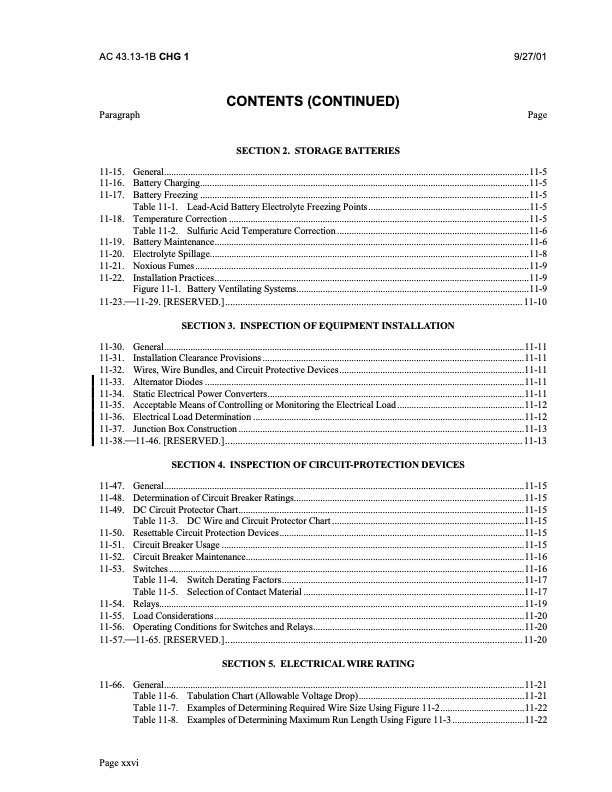
AC 43.13-1B CHG 1 9/27/01 Paragraph CONTENTS (CONTINUED) SECTION 2. STORAGE BATTERIES Page 11-15. General........................................................................................................................................................11-5 11-16. Battery Charging.........................................................................................................................................11-5 11-17. Battery Freezing .........................................................................................................................................11-5 Table 11-1. Lead-Acid Battery Electrolyte Freezing Points...................................................................11-5 11-18. Temperature Correction .............................................................................................................................11-5 Table 11-2. Sulfuric Acid Temperature Correction ................................................................................11-6 11-19. Battery Maintenance...................................................................................................................................11-6 11-20. Electrolyte Spillage.....................................................................................................................................11-8 11-21. Noxious Fumes ...........................................................................................................................................11-9 11-22. Installation Practices...................................................................................................................................11-9 Figure11-1. BatteryVentilatingSystems.................................................................................................11-9 11-23.11-29. [RESERVED.]......................................................................................................................11-10 SECTION 3. INSPECTION OF EQUIPMENT INSTALLATION 11-30. General......................................................................................................................................................11-11 11-31. Installation Clearance Provisions .............................................................................................................11-11 11-32. Wires, Wire Bundles, and Circuit Protective Devices.............................................................................11-11 11-33. Alternator Diodes .....................................................................................................................................11-11 11-34. Static Electrical Power Converters...........................................................................................................11-11 11-35. Acceptable Means of Controlling or Monitoring the Electrical Load .....................................................11-12 11-36. Electrical Load Determination .................................................................................................................11-12 11-37. Junction Box Construction .......................................................................................................................11-13 11-38.11-46. [RESERVED.]......................................................................................................................11-13 SECTION 4. INSPECTION OF CIRCUIT-PROTECTION DEVICES 11-47. General......................................................................................................................................................11-15 11-48. Determination of Circuit Breaker Ratings................................................................................................11-15 11-49. DC Circuit Protector Chart.......................................................................................................................11-15 Table 11-3. DC Wire and Circuit Protector Chart ................................................................................11-15 11-50. Resettable Circuit Protection Devices......................................................................................................11-15 11-51. Circuit Breaker Usage ..............................................................................................................................11-15 11-52. Circuit Breaker Maintenance....................................................................................................................11-16 11-53. Switches ....................................................................................................................................................11-16 Table 11-4. Switch Derating Factors.....................................................................................................11-17 Table 11-5. Selection of Contact Material ............................................................................................11-17 11-54. Relays........................................................................................................................................................11-19 11-55. Load Considerations .................................................................................................................................11-20 11-56. Operating Conditions for Switches and Relays........................................................................................11-20 11-57.11-65. [RESERVED.]......................................................................................................................11-20 SECTION5. ELECTRICALWIRERATING 11-66. General......................................................................................................................................................11-21 Page xxvi Table 11-6. Table 11-7. Table 11-8. Tabulation Chart (Allowable Voltage Drop).....................................................................11-21 Examples of Determining Required Wire Size Using Figure 11-2...................................11-22 Examples of Determining Maximum Run Length Using Figure 11-3 ..............................11-22PDF Image | AFS-640

PDF Search Title:
AFS-640Original File Name Searched:
ac_43.13-1b_w-chg1.pdfDIY PDF Search: Google It | Yahoo | Bing
5,000 BF Shipping Container Lumber Dry Kiln For Quality Lumber The 5,000 BF container kiln consists of one 40 foot high-cube aluminum shipping container... More Info
Shipping Container Lumber Dry Kilns by Global Energy Global Energy designed and developed the container kiln back in 1991. The purpose is to give access to portable sawmill owners, furniture makers, and small business the value added profit of dry kiln lumber and quality hardwoods... More Info
Vacuum Kiln Conversion Kit for Lumber and Wood Dry Kilns Convert your existing conventional dry kiln into a fast drying vacuum kiln. Similar to vacuum bagging in the boat building and aircraft industry, we have come up with a proprietary process which allows you to build a very simple vacuum kiln at a fraction of the price, and without the intensive conventional metal chamber structure... More Info
Vacuum Pump Cart System for Bagging Clamping Wood Drying and more Vacuum Cart with 2HP Pump and Dual Pistons with multiple multiplex vacuum ports and liquid reservoir... More Info
Vacuum Bagging Basics Vacuum bagging is a method of clamping, which has traditionally been used in the composites industry, but can also be used for vacuum drying materials, including wood products... More Info
| CONTACT TEL: 608-238-6001 Email: greg@globalmicroturbine.com | RSS | AMP |