PDF Publication Title:
Text from PDF Page: 011
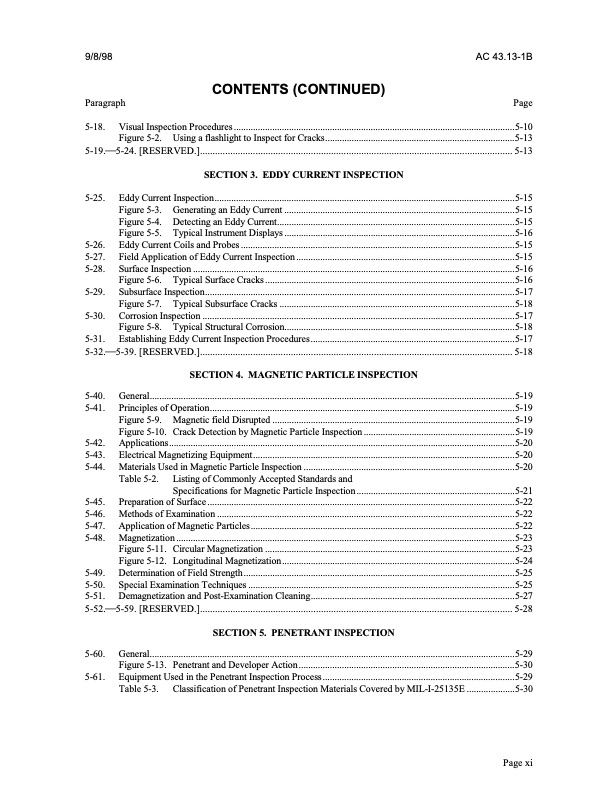
9/8/98 AC 43.13-1B Paragraph Page CONTENTS (CONTINUED) 5-18. Visual Inspection Procedures .....................................................................................................................5-10 Figure 5-2. Using a flashlight to Inspect for Cracks...............................................................................5-13 5-19.5-24. [RESERVED.]............................................................................................................................ 5-13 SECTION3. EDDYCURRENTINSPECTION 5-25. Eddy Current Inspection.............................................................................................................................5-15 Figure 5-3. Figure 5-4. Figure 5-5. Generating an Eddy Current ................................................................................................5-15 Detecting an Eddy Current...................................................................................................5-15 Typical Instrument Displays ................................................................................................5-16 5-26. Eddy Current Coils and Probes ..................................................................................................................5-15 5-27. Field Application of Eddy Current Inspection ...........................................................................................5-15 5-28. Surface Inspection ......................................................................................................................................5-16 Figure 5-6. Typical Surface Cracks ........................................................................................................5-16 5-29. Subsurface Inspection.................................................................................................................................5-17 Figure 5-7. Typical Subsurface Cracks ..................................................................................................5-18 5-30. Corrosion Inspection ..................................................................................................................................5-17 Figure 5-8. Typical Structural Corrosion................................................................................................5-18 5-31. Establishing Eddy Current Inspection Procedures.....................................................................................5-17 5-32.5-39. [RESERVED.]............................................................................................................................ 5-18 SECTION 4. MAGNETIC PARTICLE INSPECTION 5-40. General........................................................................................................................................................5-19 5-41. Principles of Operation...............................................................................................................................5-19 Figure 5-9. Magnetic field Disrupted .....................................................................................................5-19 Figure5-10. CrackDetectionbyMagneticParticleInspection...............................................................5-19 5-42. Applications ................................................................................................................................................ 5-20 5-43. Electrical Magnetizing Equipment .............................................................................................................5-20 5-44. Materials Used in Magnetic Particle Inspection ........................................................................................5-20 Table 5-2. Listing of Commonly Accepted Standards and Specifications for Magnetic Particle Inspection ..................................................................5-21 5-45. Preparation of Surface ................................................................................................................................5-22 5-46. Methods of Examination ............................................................................................................................5-22 5-47. Application of Magnetic Particles..............................................................................................................5-22 5-48. Magnetization .............................................................................................................................................5-23 Figure5-11. CircularMagnetization........................................................................................................5-23 Figure5-12. LongitudinalMagnetization.................................................................................................5-24 5-49. Determination of Field Strength .................................................................................................................5-25 5-50. Special Examination Techniques ...............................................................................................................5-25 5-51. Demagnetization and Post-Examination Cleaning.....................................................................................5-27 5-52.5-59. [RESERVED.]............................................................................................................................ 5-28 SECTION 5. PENETRANT INSPECTION 5-60. General........................................................................................................................................................5-29 Figure 5-13. Penetrant and Developer Action..........................................................................................5-30 5-61. Equipment Used in the Penetrant Inspection Process................................................................................5-29 Table 5-3. Classification of Penetrant Inspection Materials Covered by MIL-I-25135E ....................5-30 Page xiPDF Image | AFS-640

PDF Search Title:
AFS-640Original File Name Searched:
ac_43.13-1b_w-chg1.pdfDIY PDF Search: Google It | Yahoo | Bing
5,000 BF Shipping Container Lumber Dry Kiln For Quality Lumber The 5,000 BF container kiln consists of one 40 foot high-cube aluminum shipping container... More Info
Shipping Container Lumber Dry Kilns by Global Energy Global Energy designed and developed the container kiln back in 1991. The purpose is to give access to portable sawmill owners, furniture makers, and small business the value added profit of dry kiln lumber and quality hardwoods... More Info
Vacuum Kiln Conversion Kit for Lumber and Wood Dry Kilns Convert your existing conventional dry kiln into a fast drying vacuum kiln. Similar to vacuum bagging in the boat building and aircraft industry, we have come up with a proprietary process which allows you to build a very simple vacuum kiln at a fraction of the price, and without the intensive conventional metal chamber structure... More Info
Vacuum Pump Cart System for Bagging Clamping Wood Drying and more Vacuum Cart with 2HP Pump and Dual Pistons with multiple multiplex vacuum ports and liquid reservoir... More Info
Vacuum Bagging Basics Vacuum bagging is a method of clamping, which has traditionally been used in the composites industry, but can also be used for vacuum drying materials, including wood products... More Info
| CONTACT TEL: 608-238-6001 Email: greg@globalmicroturbine.com | RSS | AMP |