PDF Publication Title:
Text from PDF Page: 054
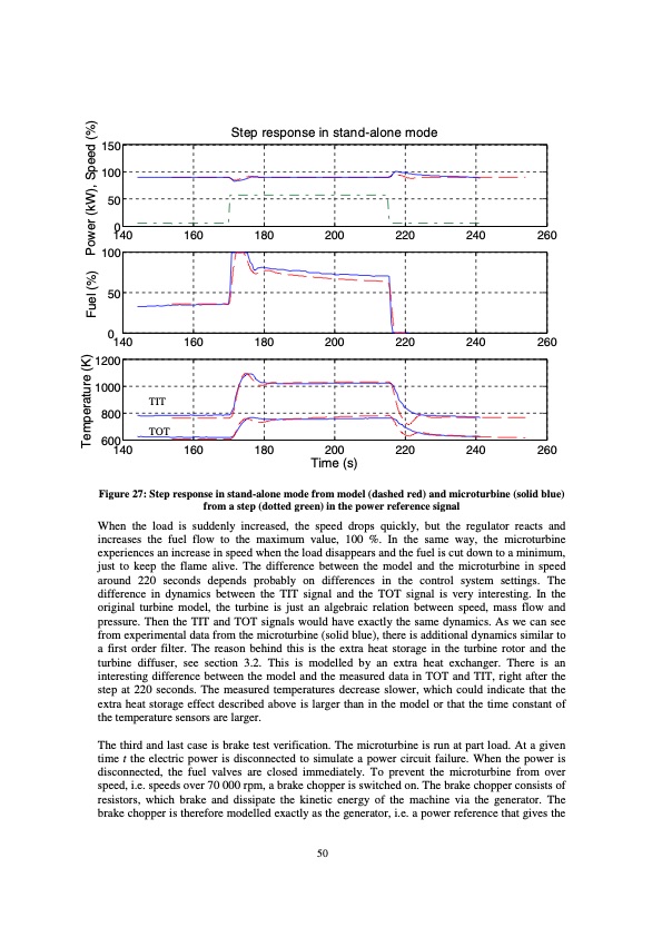
150 100 50 0 140 160 180 200 100 50 0 140 160 180 200 1200 1000 800 600 140 160 180 200 Time (s) 220 240 260 220 240 260 220 240 260 Step response in stand-alone mode TIT TOT Figure 27: Step response in stand-alone mode from model (dashed red) and microturbine (solid blue) from a step (dotted green) in the power reference signal When the load is suddenly increased, the speed drops quickly, but the regulator reacts and increases the fuel flow to the maximum value, 100 %. In the same way, the microturbine experiences an increase in speed when the load disappears and the fuel is cut down to a minimum, just to keep the flame alive. The difference between the model and the microturbine in speed around 220 seconds depends probably on differences in the control system settings. The difference in dynamics between the TIT signal and the TOT signal is very interesting. In the original turbine model, the turbine is just an algebraic relation between speed, mass flow and pressure. Then the TIT and TOT signals would have exactly the same dynamics. As we can see from experimental data from the microturbine (solid blue), there is additional dynamics similar to a first order filter. The reason behind this is the extra heat storage in the turbine rotor and the turbine diffuser, see section 3.2. This is modelled by an extra heat exchanger. There is an interesting difference between the model and the measured data in TOT and TIT, right after the step at 220 seconds. The measured temperatures decrease slower, which could indicate that the extra heat storage effect described above is larger than in the model or that the time constant of the temperature sensors are larger. The third and last case is brake test verification. The microturbine is run at part load. At a given time t the electric power is disconnected to simulate a power circuit failure. When the power is disconnected, the fuel valves are closed immediately. To prevent the microturbine from over speed, i.e. speeds over 70 000 rpm, a brake chopper is switched on. The brake chopper consists of resistors, which brake and dissipate the kinetic energy of the machine via the generator. The brake chopper is therefore modelled exactly as the generator, i.e. a power reference that gives the 50 Temperature (K) Fuel (%) Power (kW), Speed (%)PDF Image | Modelling of Microturbine Systems
PDF Search Title:
Modelling of Microturbine SystemsOriginal File Name Searched:
Model_turbiny_T100.pdfDIY PDF Search: Google It | Yahoo | Bing
Capstone Turbine and Microturbine: Capstone microturbines used and new surplus for sale listing More Info
Consulting and Strategy Services: Need help with Capstone Turbine, sizing systems, applications, or renewable energy strategy, we are here to assist More Info
Container Lumber Dry Kiln: Since 1991 developing and innovating dry kilns using standard shipping containers More Info
Supercritical CO2 Lumber Dry Kiln: Compact fast drying in 3 days or less for small amounts of wood and lumber drying More Info
BitCoin Mining: Bitcoin Mining and Cryptocurrency... More Info
Publications: Capstone Turbine publications for microturbine and distributed energy More Info
FileMaker Software for Renewable Energy Developing database software for the renewable energy industry More Info
CO2 Gas to Liquids On-Demand Production Cart Developing a supercritical CO2 to alcohol on-demand production system (via Nafion reverse fuel cell) More Info
Stranded Gas for low cost power Bitcoin Mining Using stranded gas for generators may provide breakthrough low power costs for cryptocurrency miners. More Info
| CONTACT TEL: 608-238-6001 Email: greg@globalmicroturbine.com | RSS | AMP |