PDF Publication Title:
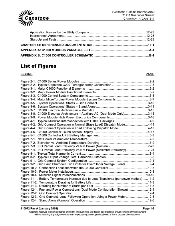
Text from PDF Page: 008
CAPSTONE TURBINE CORPORATION 21211 NORDHOFF STREET Capstone CHATSWORTH, CA 91311 Application Review by the Utility Company .................................................................12-23 Interconnect Agreement..............................................................................................12-23 Start-Up and Tests ......................................................................................................12-23 CHAPTER 13: REFERENCED DOCUMENTATION...............................................................13-1 APPENDIX A: C1000 MODBUS VARIABLE LIST .................................................................. A-1 APPENDIX B: C1000 CONTROLLER SCHEMATIC ............................................................... B-1 List of Figures FIGURE PAGE Figure 2-1. C1000 Series Power Modules ................................................................................2-2 Figure 2-2. Typical Capstone C200 Turbogenerator Construction ...........................................2-3 Figure 3-1. Major C1000 Functional Elements .........................................................................3-2 Figure 3-2. Major Power Module Functional Elements .............................................................3-2 Figure 3-3. C1000 Control System Components ......................................................................3-5 Figure 3-4. Major MicroTurbine Power Module System Components ......................................3-7 Figure 3-5. System Operational States – Grid Connect..........................................................3-10 Figure 3-6. System Operational States – Stand Alone ...........................................................3-11 Figure 3-7. C1000 Electrical Architecture – Main AC .............................................................3-15 Figure 3-8. C1000 Electrical Architecture – Auxiliary AC (Dual Mode Only)...........................3-15 Figure 3-9. Power Module High Power Electronics Components ...........................................3-16 Figure 4-1. Typical MultiPac Interconnection with C1000 Packages ........................................4-9 Figure 4-2. Grid Connect Operation in Normal (Base Load) Dispatch Mode..........................4-11 Figure 4-4. Grid Connect Operation in Load Following Dispatch Mode..................................4-13 Figure 4-5. C1000 Controller Touch Screen Display ..............................................................4-17 Figure 5-1. C1000 Controller UPS Battery Management..........................................................5-3 Figure 7-1. Net Power vs Ambient Temperature ......................................................................7-2 Figure 7-2. Elevation vs. Ambient Temperature Derating.........................................................7-9 Figure 7-3. ISO Partial Load Efficiency Vs Net Power (Nominal) ...........................................7-23 Figure 7-4. ISO Partial Load Efficiency Vs Net Power (Maximum Efficiency).........................7-24 Figure 8-1. Typical Total Harmonic Current..............................................................................8-4 Figure 8-2. Typical Output Voltage Total Harmonic Distortion..................................................8-8 Figure 9-1. Grid Connect System Configuration .......................................................................9-1 Figure 9-2. Grid Fault Shutdown Trip Limits for Over/Under Voltage Events ...........................9-4 Figure 10-2. Connection Locations within the C1000 Controller.............................................10-3 Figure 10-3. Power Meter installation .....................................................................................10-8 Figure 10-4. MultiPac Signal Interconnections .....................................................................10-10 Figure 11-1. Battery Temperature Increase due to Load Transients (per power module)......11-2 Figure 11-2. Temperature Derating for Battery Life ................................................................11-3 Figure 11-3. Derating for Number of Starts per Year..............................................................11-3 Figure 12-1. Fuel and Power Connections (Dual Mode Configuration Shown) ......................12-1 Figure 12-2. Grid Connect Operation......................................................................................12-4 Figure 12-3. Grid Connect, Load-Following Operation Using a Power Meter.........................12-5 Figure 12-4. Stand Alone (Remote) Operation .......................................................................12-6 410072 Rev A (January 2009) Page 1-6 Capstone reserves the right to change or modify, without notice, the design, specifications, and/or contents of this document without incurring any obligation either with respect to equipment previously sold or in the process of construction.PDF Image | CAPSTONE C1000 MICROTURBINE SYSTEMS TECHNICAL REFERENCE

PDF Search Title:
CAPSTONE C1000 MICROTURBINE SYSTEMS TECHNICAL REFERENCEOriginal File Name Searched:
410072A_C1000_TR.pdfDIY PDF Search: Google It | Yahoo | Bing
Capstone Turbine and Microturbine: Capstone microturbines used and new surplus for sale listing More Info
Consulting and Strategy Services: Need help with Capstone Turbine, sizing systems, applications, or renewable energy strategy, we are here to assist More Info
Container Lumber Dry Kiln: Since 1991 developing and innovating dry kilns using standard shipping containers More Info
Supercritical CO2 Lumber Dry Kiln: Compact fast drying in 3 days or less for small amounts of wood and lumber drying More Info
BitCoin Mining: Bitcoin Mining and Cryptocurrency... More Info
Publications: Capstone Turbine publications for microturbine and distributed energy More Info
FileMaker Software for Renewable Energy Developing database software for the renewable energy industry More Info
CO2 Gas to Liquids On-Demand Production Cart Developing a supercritical CO2 to alcohol on-demand production system (via Nafion reverse fuel cell) More Info
Stranded Gas for low cost power Bitcoin Mining Using stranded gas for generators may provide breakthrough low power costs for cryptocurrency miners. More Info
| CONTACT TEL: 608-238-6001 Email: greg@globalmicroturbine.com | RSS | AMP |