PDF Publication Title:
Text from PDF Page: 005
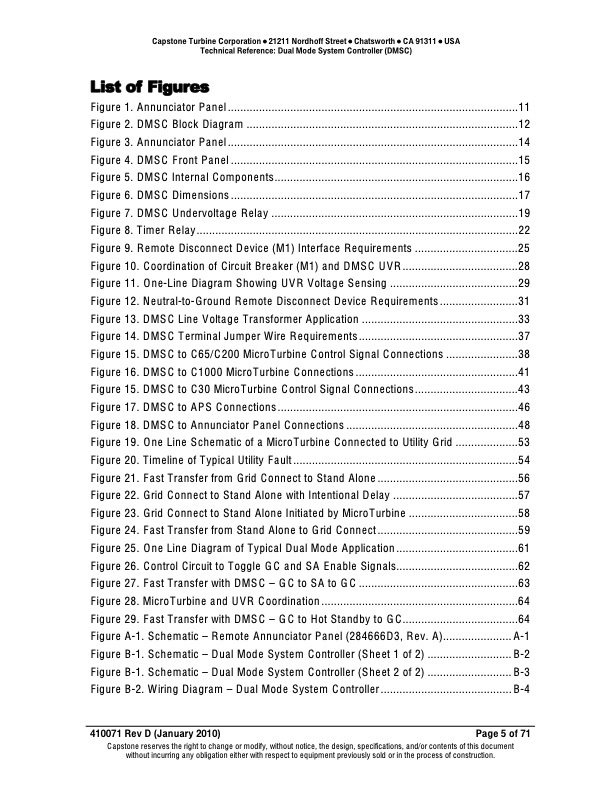
Capstone Turbine Corporation • 21211 Nordhoff Street • Chatsworth • CA 91311 • USA Technical Reference: Dual Mode System Controller (DMSC) List of Figures Figure 1. Annunciator Panel .............................................................................................11 Figure 2. DMSC Block Diagram .......................................................................................12 Figure 3. Annunciator Panel .............................................................................................14 Figure 4. DMSC Front Panel ............................................................................................15 Figure 5. DMSC Internal Components..............................................................................16 Figure 6. DMSC Dimensions ............................................................................................17 Figure 7. DMSC Undervoltage Relay ...............................................................................19 Figure 8. Timer Relay.......................................................................................................22 Figure 9. Remote Disconnect Device (M1) Interface Requirements .................................25 Figure 10. Coordination of Circuit Breaker (M1) and DMSC UVR.....................................28 Figure 11. One-Line Diagram Showing UVR Voltage Sensing .........................................29 Figure 12. Neutral-to-Ground Remote Disconnect Device Requirements .........................31 Figure 13. DMSC Line Voltage Transformer Application ..................................................33 Figure 14. DMSC Terminal Jumper Wire Requirements...................................................37 Figure 15. DMSC to C65/C200 MicroTurbine Control Signal Connections .......................38 Figure 16. DMSC to C1000 MicroTurbine Connections ....................................................41 Figure 15. DMSC to C30 MicroTurbine Control Signal Connections.................................43 Figure 17. DMSC to APS Connections.............................................................................46 Figure 18. DMSC to Annunciator Panel Connections .......................................................48 Figure 19. One Line Schematic of a MicroTurbine Connected to Utility Grid ....................53 Figure 20. Timeline of Typical Utility Fault ........................................................................54 Figure 21. Fast Transfer from Grid Connect to Stand Alone.............................................56 Figure 22. Grid Connect to Stand Alone with Intentional Delay ........................................57 Figure 23. Grid Connect to Stand Alone Initiated by MicroTurbine ...................................58 Figure 24. Fast Transfer from Stand Alone to Grid Connect.............................................59 Figure 25. One Line Diagram of Typical Dual Mode Application.......................................61 Figure 26. Control Circuit to Toggle GC and SA Enable Signals.......................................62 Figure 27. Fast Transfer with DMSC – GC to SA to GC ...................................................63 Figure 28. MicroTurbine and UVR Coordination ...............................................................64 Figure 29. Fast Transfer with DMSC – GC to Hot Standby to GC.....................................64 Figure A-1. Schematic – Remote Annunciator Panel (284666D3, Rev. A)......................A-1 Figure B-1. Schematic – Dual Mode System Controller (Sheet 1 of 2) ........................... B-2 Figure B-1. Schematic – Dual Mode System Controller (Sheet 2 of 2) ........................... B-3 Figure B-2. Wiring Diagram – Dual Mode System Controller .......................................... B-4 410071 Rev D (January 2010) Page 5 of 71 Capstone reserves the right to change or modify, without notice, the design, specifications, and/or contents of this document without incurring any obligation either with respect to equipment previously sold or in the process of construction.PDF Image | Dual Mode System Controller DMSC

PDF Search Title:
Dual Mode System Controller DMSCOriginal File Name Searched:
410071D_Dual_Mode_System_Controller_DMSC_TR.pdfDIY PDF Search: Google It | Yahoo | Bing
Capstone Turbine and Microturbine: Capstone microturbines used and new surplus for sale listing More Info
Consulting and Strategy Services: Need help with Capstone Turbine, sizing systems, applications, or renewable energy strategy, we are here to assist More Info
Container Lumber Dry Kiln: Since 1991 developing and innovating dry kilns using standard shipping containers More Info
Supercritical CO2 Lumber Dry Kiln: Compact fast drying in 3 days or less for small amounts of wood and lumber drying More Info
BitCoin Mining: Bitcoin Mining and Cryptocurrency... More Info
Publications: Capstone Turbine publications for microturbine and distributed energy More Info
FileMaker Software for Renewable Energy Developing database software for the renewable energy industry More Info
CO2 Gas to Liquids On-Demand Production Cart Developing a supercritical CO2 to alcohol on-demand production system (via Nafion reverse fuel cell) More Info
Stranded Gas for low cost power Bitcoin Mining Using stranded gas for generators may provide breakthrough low power costs for cryptocurrency miners. More Info
| CONTACT TEL: 608-238-6001 Email: greg@globalmicroturbine.com | RSS | AMP |